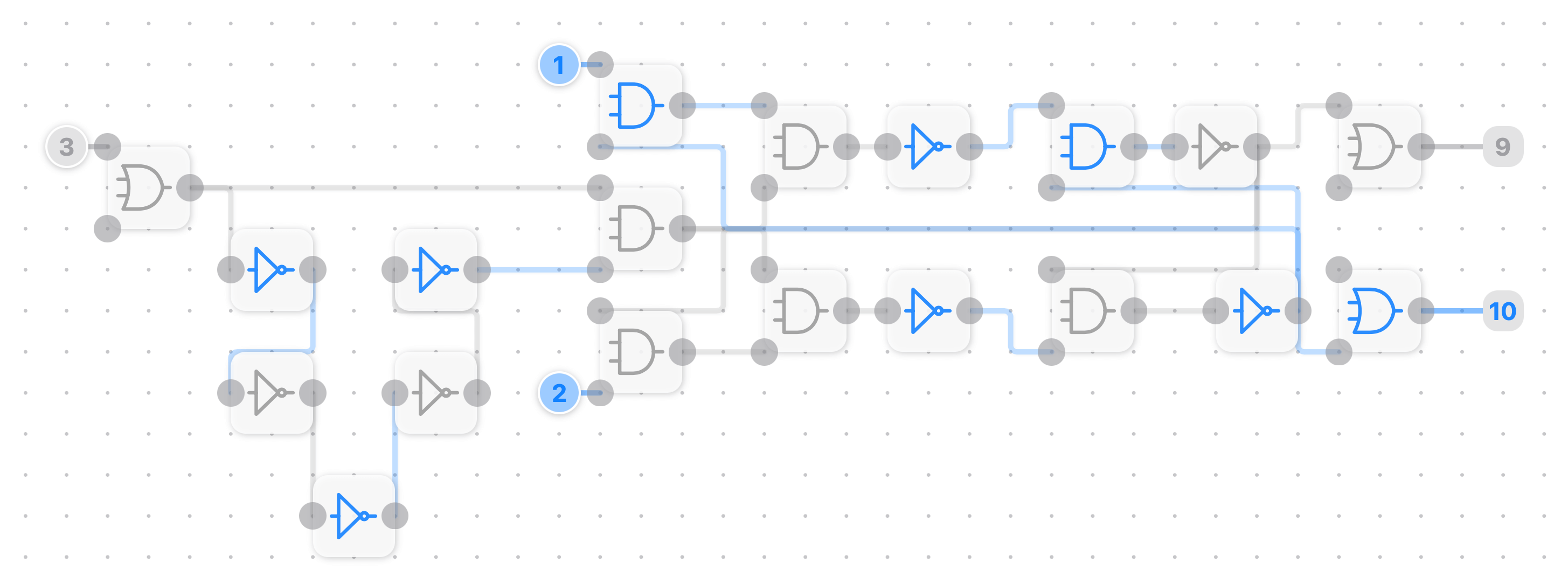
1. D flip-flop
In electronics, a flip-flop or latch is a circuit that has two stable states and can be used to store state information. Flip-flops and latches are fundamental building blocks of digital electronic systems used in computers, communications, and many other types of systems Wiki.
This example uses a short delay line to create signal edge detection a technique widely used in embedded software, model-based development and electronics.
We will make this board as a reusable package to build a more complex circuit.
Here is the exported file. Save and open with the LogicalArt or try build one by yourself in the AppClip.
2. Package and reusing your circuit
Here is the exported file. Save and open with the LogicalArt.
3. Memory
A time-lapse about how to build a 32-bit memory in LogicalArt on YouTube.
In LogicalArt you can make a circuit by tapping to write every input and output combination. In hardware, EEPROM is an electronic device that can be erased and reprogrammed.
Here is the exported file. Save and open with the LogicalArt.
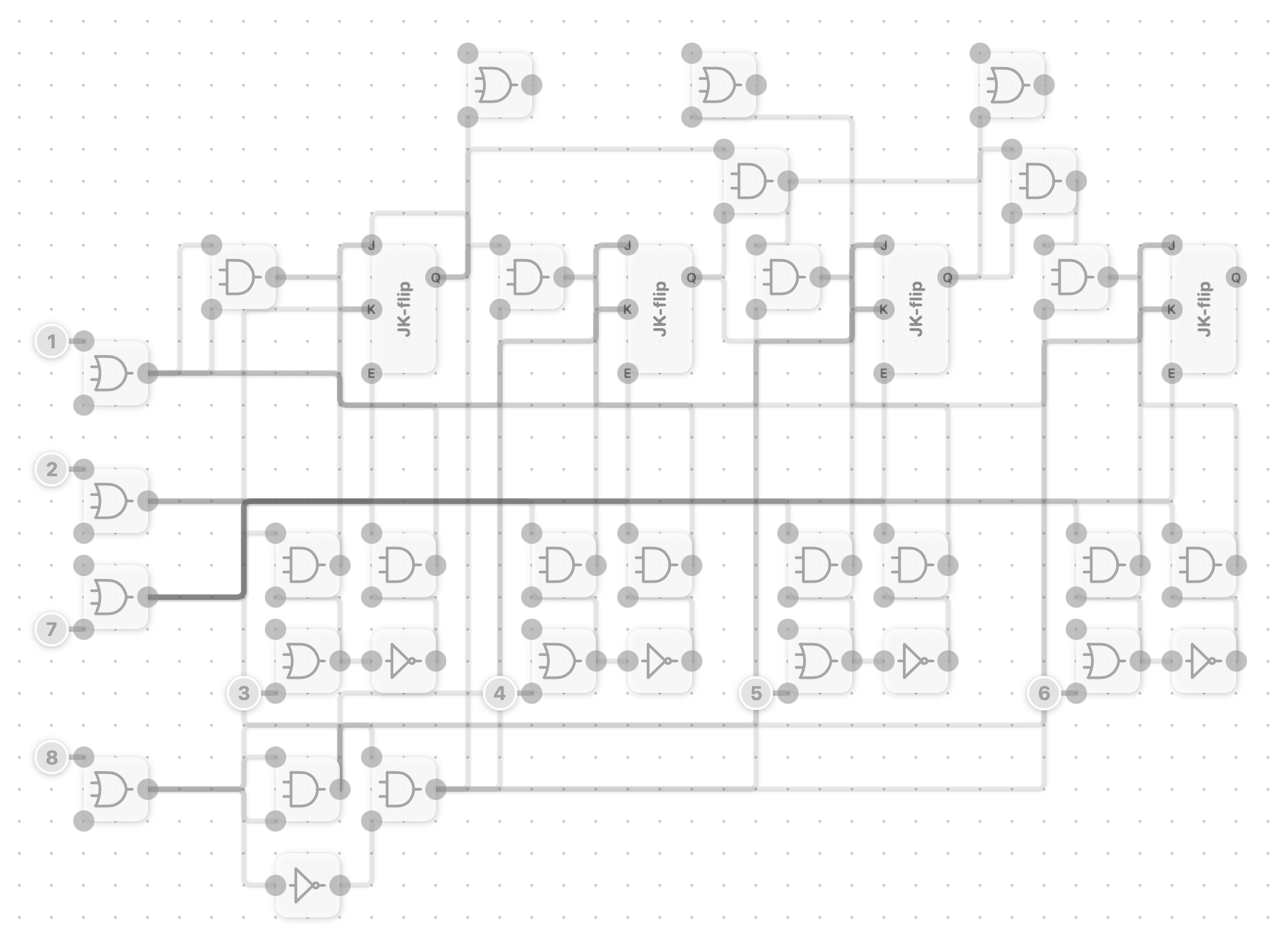
4. Program counter
To execute the instruction by order, we need count, set and reset the location(address).Link
We use theJK flip flopwhich prevents the illegal or invalid output condition that can occur on SR flip Flop.
Here is the exported file.
----
This is how to link the JK flip to make it not only count but can start from any setting address.
Here is the exported file.
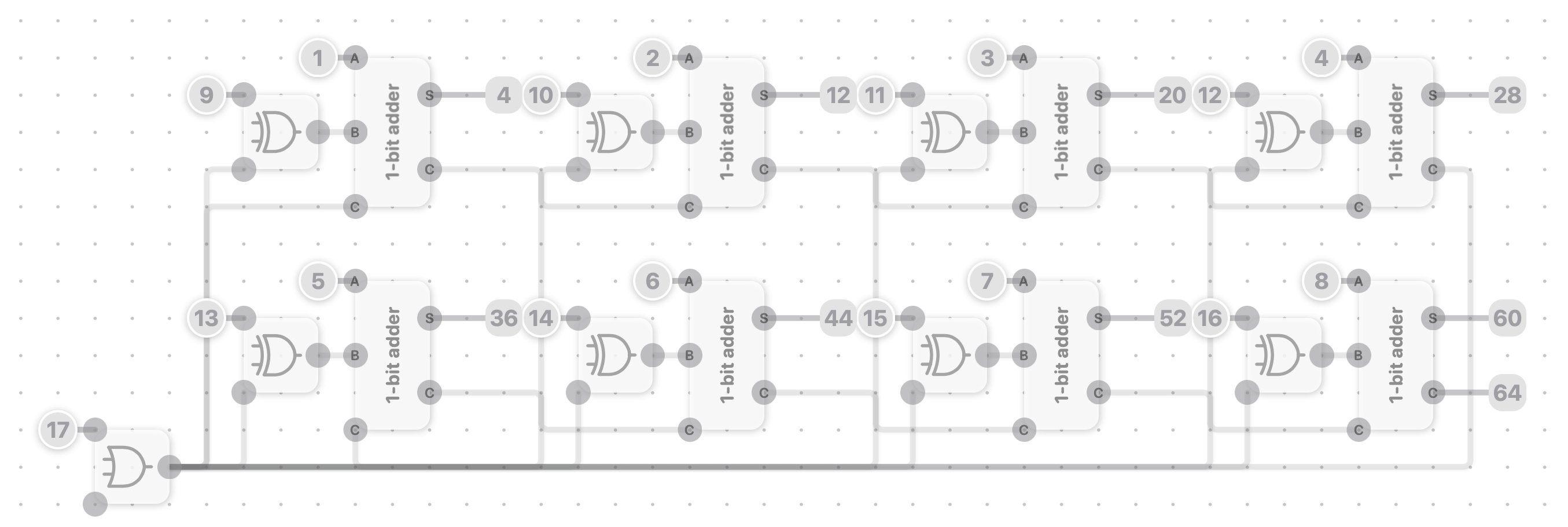
5. ALU
Build a full adder on Mac.
Two's complement is the most common method of representing signed integers on computers. Below demonstrated how to build 1-bit adder by using logic gate.
The Mac version LogicalArt has the same features on iPad and take the advantage of keyboard, mouse wheel and big screen on computer. Here are some shortcut:
Zoom : ⌘+ (=/- or ScrollWheel);
Show/hide panels: ⌘+f;
Delete(when selected):⌫;
Undo: ⌘+z;
New board:⌘+n;
Open:⌘+o;
Export:⌘+s;
Info:⌘+i;
----
Below demonstrated how to assemble 1-bit adders to an ALU. The Input-17 is a subtraction indicator. The Output-64 is a flag.
Here is the exported file.
6. Assemble the component
Below are some additional chips that will use to assemble the computer.
The link will be used to link the module to the bridge.
Bridge the system bridge (modules communicate with each other by that).
Edge Detection will output 1 when detecting the rising edge of the clock.
Zero Flag will output 1 when input is 8-bit zero.
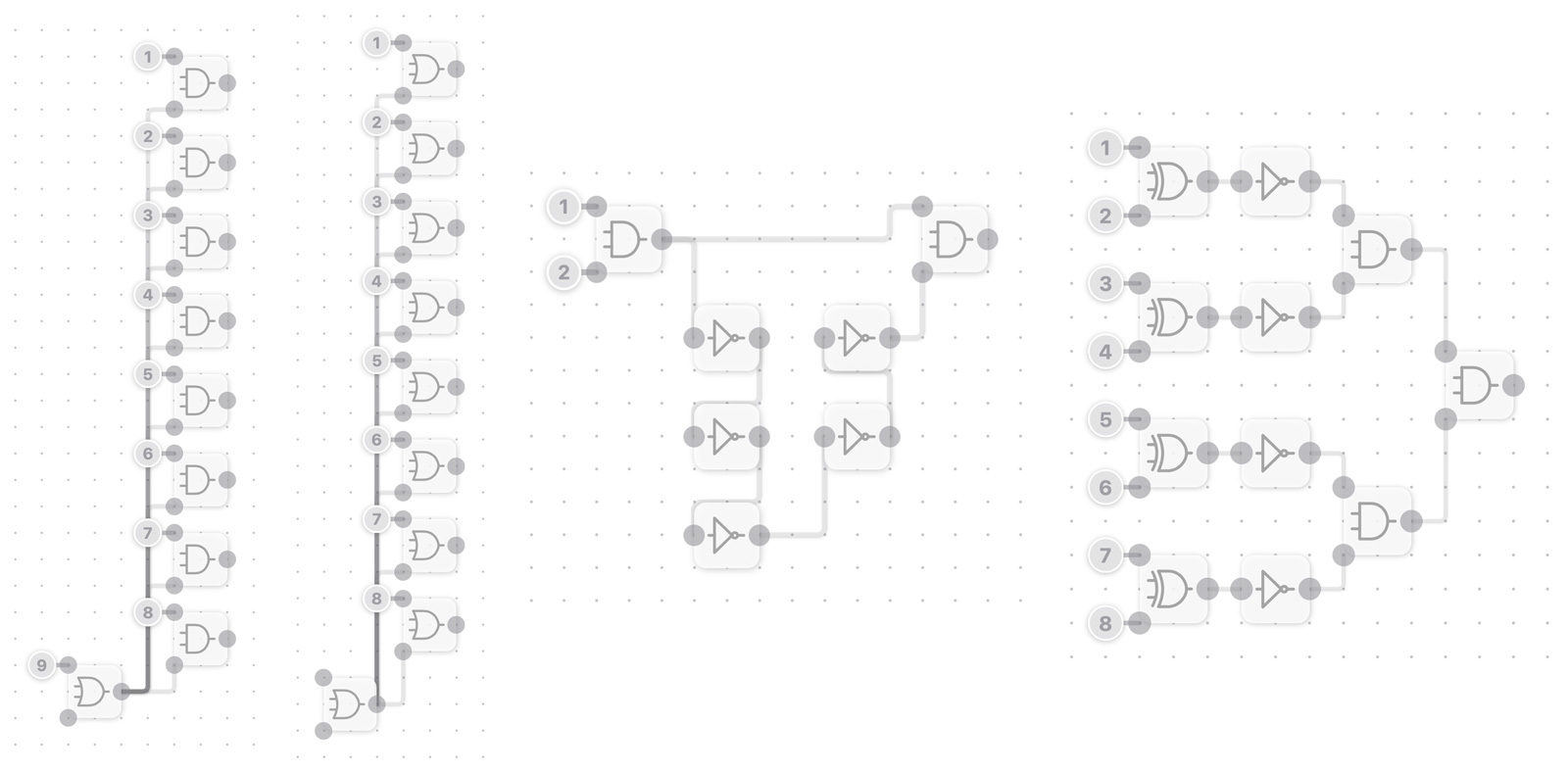
Link / Bridge / Edge Detection / Zero Flag
----
Now we can assemble the chips together and link them to the bridge and build a controller with an instruction set.
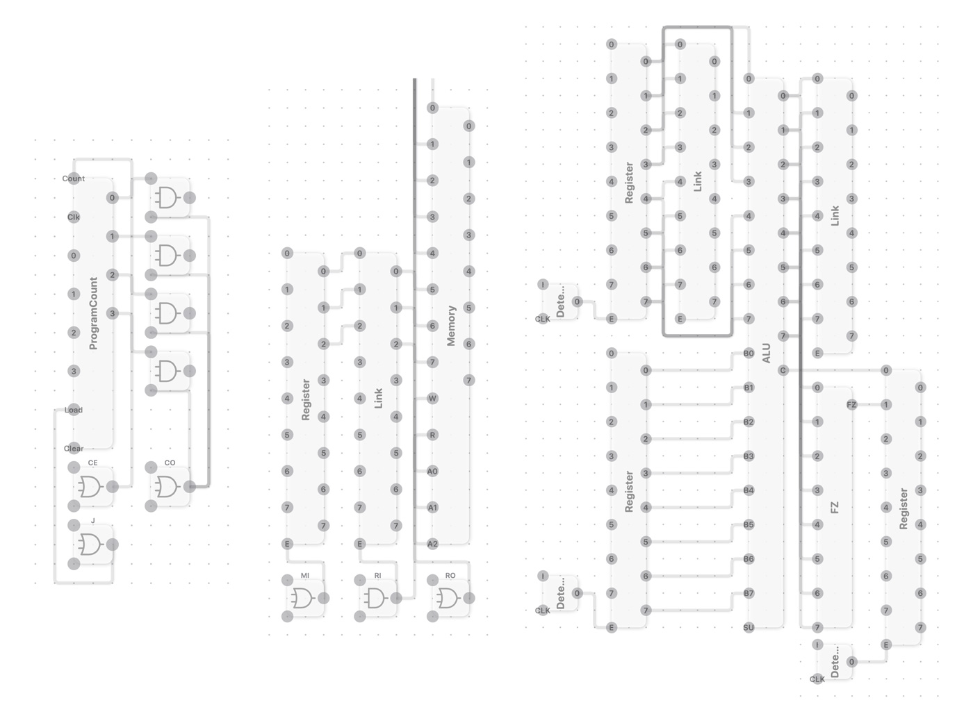
Program Count / Memory / ALU
----
In the instruction controller, I hardwire the fetch steps and create the instruction decoder with EEPROM.

Below are instruction codes I will use which come from Ben Eater's video -Conditional jump instructions.
| Instruction | Step | CF | ZF | HLT | MI | RI | RO | IO | II | AI | AO | EO | SU | BI | OI | CE | CO | J | FI | ||
|---|---|---|---|---|---|---|---|---|---|---|---|---|---|---|---|---|---|---|---|---|---|
| Fetch | XXXX | 000 | X | X | 0 | 1 | 0 | 0 | 0 | 0 | 0 | 0 | 0 | 0 | 0 | 0 | 0 | 1 | 0 | 0 | |
| XXXX | 001 | X | X | 0 | 0 | 0 | 1 | 0 | 1 | 0 | 0 | 0 | 0 | 0 | 0 | 1 | 0 | 0 | 0 | ||
| LDA | 0001 | 010 | X | X | 0 | 1 | 0 | 0 | 1 | 0 | 0 | 0 | 0 | 0 | 0 | 0 | 0 | 0 | 0 | 0 | |
| 0001 | 011 | X | X | 0 | 0 | 0 | 1 | 0 | 0 | 1 | 0 | 0 | 0 | 0 | 0 | 0 | 0 | 0 | 0 | ||
| 0001 | 100 | X | X | 0 | 0 | 0 | 0 | 0 | 0 | 0 | 0 | 0 | 0 | 0 | 0 | 0 | 0 | 0 | 0 | ||
| ADD | 0010 | 010 | X | X | 0 | 1 | 0 | 0 | 1 | 0 | 0 | 0 | 0 | 0 | 0 | 0 | 0 | 0 | 0 | 0 | |
| 0010 | 011 | X | X | 0 | 0 | 0 | 1 | 0 | 0 | 0 | 0 | 0 | 0 | 1 | 0 | 0 | 0 | 0 | 0 | ||
| 0010 | 100 | X | X | 0 | 0 | 0 | 0 | 0 | 0 | 1 | 0 | 1 | 0 | 0 | 0 | 0 | 0 | 0 | 1 | ||
| SUB | 0011 | 010 | X | X | 0 | 1 | 0 | 0 | 1 | 0 | 0 | 0 | 0 | 0 | 0 | 0 | 0 | 0 | 0 | 0 | |
| 0011 | 011 | X | X | 0 | 0 | 0 | 1 | 0 | 0 | 0 | 0 | 0 | 0 | 1 | 0 | 0 | 0 | 0 | 0 | ||
| 0011 | 100 | X | X | 0 | 0 | 0 | 0 | 0 | 0 | 1 | 0 | 1 | 1 | 0 | 0 | 0 | 0 | 0 | 1 | ||
| STA | 0100 | 010 | X | X | 0 | 1 | 0 | 0 | 1 | 0 | 0 | 0 | 0 | 0 | 0 | 0 | 0 | 0 | 0 | 0 | |
| 0100 | 011 | X | X | 0 | 0 | 1 | 0 | 0 | 0 | 0 | 1 | 0 | 0 | 0 | 0 | 0 | 0 | 0 | 0 | ||
| 0100 | 100 | X | X | 0 | 0 | 0 | 0 | 0 | 0 | 0 | 0 | 0 | 0 | 0 | 0 | 0 | 0 | 0 | 0 | ||
| LDI | 0101 | 010 | X | X | 0 | 0 | 0 | 0 | 1 | 0 | 1 | 0 | 0 | 0 | 0 | 0 | 0 | 0 | 0 | 0 | |
| 0101 | 011 | X | X | 0 | 0 | 0 | 0 | 0 | 0 | 0 | 0 | 0 | 0 | 0 | 0 | 0 | 0 | 0 | 0 | ||
| JMP | 0110 | 010 | X | X | 0 | 0 | 0 | 0 | 1 | 0 | 0 | 0 | 0 | 0 | 0 | 0 | 0 | 0 | 1 | 0 | |
| 0110 | 011 | X | X | 0 | 0 | 0 | 0 | 0 | 0 | 0 | 0 | 0 | 0 | 0 | 0 | 0 | 0 | 0 | 0 | ||
| JC | 0111 | 010 | 0 | X | 0 | 0 | 0 | 0 | 0 | 0 | 0 | 0 | 0 | 0 | 0 | 0 | 0 | 0 | 0 | 0 | |
| 0111 | 010 | 1 | X | 0 | 0 | 0 | 0 | 1 | 0 | 0 | 0 | 0 | 0 | 0 | 0 | 0 | 0 | 1 | 0 | ||
| 0111 | 011 | X | X | 0 | 0 | 0 | 0 | 0 | 0 | 0 | 0 | 0 | 0 | 0 | 0 | 0 | 0 | 0 | 0 | ||
| JZ | 1000 | 010 | X | 0 | 0 | 0 | 0 | 0 | 0 | 0 | 0 | 0 | 0 | 0 | 0 | 0 | 0 | 0 | 0 | 0 | |
| 1000 | 010 | X | 1 | 0 | 0 | 0 | 0 | 1 | 0 | 0 | 0 | 0 | 0 | 0 | 0 | 0 | 0 | 1 | 0 | ||
| 1000 | 011 | X | X | 0 | 0 | 0 | 0 | 0 | 0 | 0 | 0 | 0 | 0 | 0 | 0 | 0 | 0 | 0 | 0 | ||
| OUT | 1110 | 010 | X | X | 0 | 0 | 0 | 0 | 0 | 0 | 0 | 1 | 0 | 0 | 0 | 1 | 0 | 0 | 0 | 0 | |
| 1110 | 011 | X | X | 0 | 0 | 0 | 0 | 0 | 0 | 0 | 0 | 0 | 0 | 0 | 0 | 0 | 0 | 0 | 0 | ||
Now Here is my frist verion 8-bit computer in LogicalArt.